

After playing around a little bit with my new Handheld Gimbal, I noticed that there were some things that could be improved.
The results were just fine, but there were lot of room for improvements!. Comparing with commertial solution, handheld gimbals usually have a joystick that will allow the user to set a certain offset in so the important things can be kept allways in focus.
On the other hand, battery life was a little bit short eventough batteries were still with some useful remaining load.
In this second update I will describe the following points
- How to add a joystick to our gimbal
- How to make use of most of the battery load in an efficient way
- Updated gimbal configuration (I also added the file for download)
The first part of this instructable can be found here
Contents
What do you need to get started?
Make sure that you have all the components described on the first part of this instructable
- Universal Joystick für Alexmos 8/32 Bits Basecam 2/3 Achsen Gimbal
- 3A XL6009 DC-DC 50KHz Adjustable Step Up Power Converter Module
- 2 x 3.9Kohm resistor
- PVC Heat Shrink Tub 30mm / 10cm
- Male and Female JST Connector Plug Line for RC BEC Lipo Battery (Gearbest)
Adding a Joystick to the gimbal
The following figure should be used as reference, this image has been taken from www.olliw.eu .
The joystick used for this ninstructable can be found in the following link Universal Joystick für Alexmos 8/32 Bits Basecam 2/3 Achsen Gimbal

Please notice that there is one pad that is not connected after the red wire.
There are two additional wires for the buttons that I didnt connect since I dont need them. In case you want to make use of the full joystick functionality, the proceed to solder the two missing headers and connect the cables as shown in the picture above.
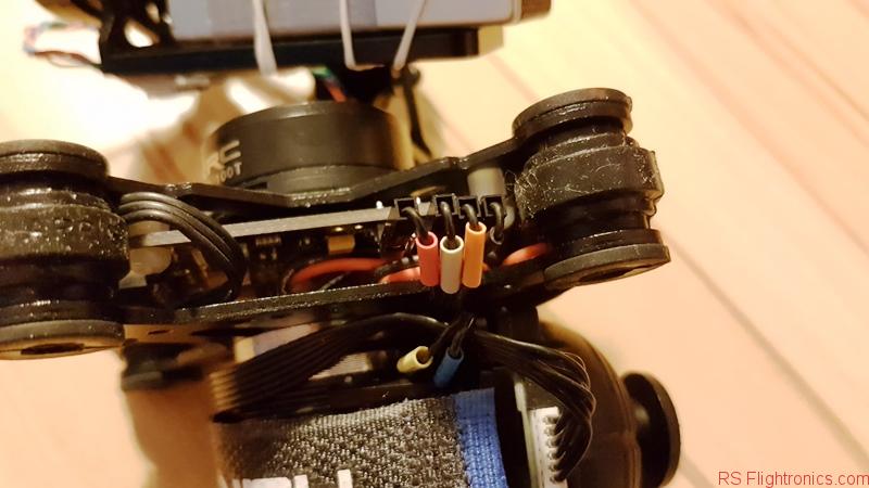
After all cable have been connected, your setup should look something similar to the figure below.
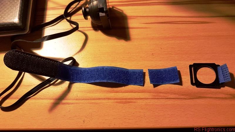
In order to get the joystick fixed, I sewed the provided camera strap and did some adaptions by cutting the solid part out and also cutting 4cm of the blue strap.
Next I sewed and glued part of the strap on the area show below.

Thank to this, the joystick can be fixed to our “flashlight” without any issues. The long cable can be hidden behind this strap or it could also be shortened, in case you really want to do it.
Joystick configuration
The basic configuration is shown below. Using the setup software described on the previous chapter of this instructable, you should configure your habdheld gimbal as follows:

This configuration will allow you to set a certain offset within a secured area where no collitions between of the gimbal and the camera should happen. Feel free to play with thes values and to find the best configuration that works for you!.
DC DC Converter – Make your battery “last longer”!
A step up DC DC converter is an electronic configuration that will convert a certain voltage value to a higher and stable one. Said with other words, it will make sure that within certain margins, we will have a constant ouput of let say 8,5v while the input voltage is any value lower than the output voltage (7,5v from our gimbal batteries). This solution works perfect for our gimbal and is widely used in nowaday electronics, since it allows to provide a stable power source until batteries are almost about to die.
For this instructable we are using the following Step up DC DC converter :3A XL6009 DC-DC 50KHz Adjustable Step Up Power Converter Module
This module has a configurable output within a wide range. Since this is a feature that is not needed in our case, we will proceed to remove the variable resistor and to replace it with a fixed value, so we also avoid to have an unexpected change of our output voltage given by an accidental or unprevisted change on the variable resistor. It is important to remark, that having a significant change on the gimbal voltage could also affect the way out PIDs values are affected!
The variable resistor is shown in the picture below. This part shall be removed.

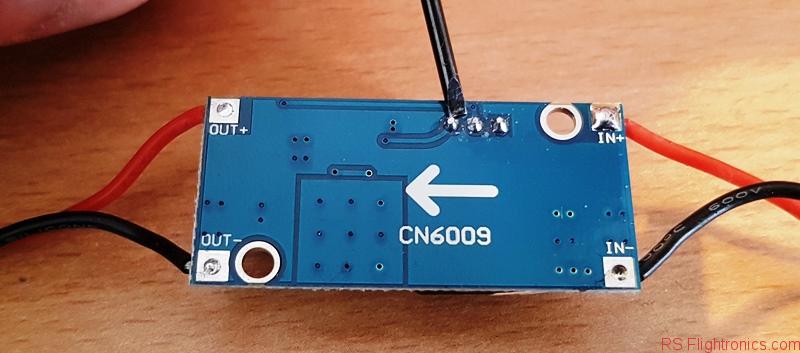
On the picture below, we see the points where we need to remove the soldered pins.
Once the variable resistor has been removed, a fixed resistor value can be soldered between the points shown in the picture below. I combined two resistors of 3,9Kohm (7.8Kohm) in order to have a fixed output of 8,5v.
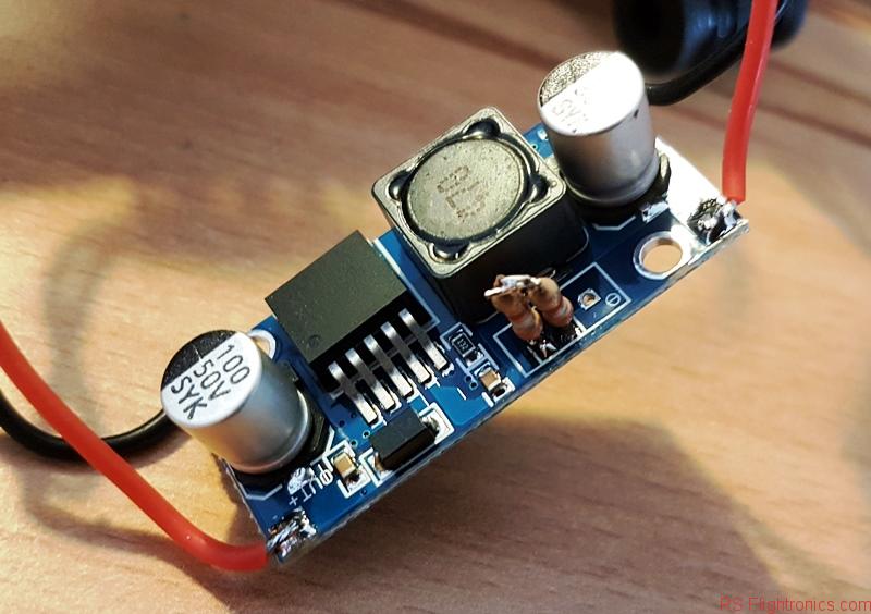
As you can see, both resistors pins have been solder together and their other terminals were soldered in the left possition of the variable resistor. This configuration emulates the variable resistor being set at 7,8Kohm, or the output voltage being set to 8,5v. The resulting value can be affected by minor deviations introduced by the resistors tolerances. This shouldn´t be a big issue.
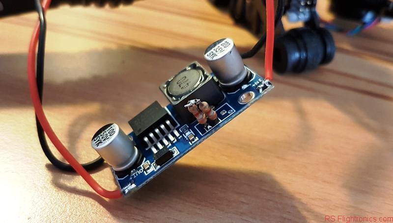
A detail from the bottom layer after the two resistors have been sodlered can be seen below:
Once our fixed resistor are soldered, we can proceed to isolate our DC DC converter. I also shortened the cables a little bit to prevent cable chaos on our setup.
For the isolation I used a 30mm PVC Heat Shrink Tub.


Once the DC DC converter is ready, it can be mounted on the gimbal. In my case I mounted it above the joystick.
Before switching the power on, make sure you have checked if polarities are right!!!

Handheld gimbal updated configurations
Since we have introduced two new components, we need to update our handheld gimbal configurations.
Our Step Up DC DC converter is now providing a higher voltage in comparison with the voltage the the gimbal was receiving directly form the batteries. The following configuration file should cover all the necessary changes or at least it can be used a starting point for your own setup:
20180302_gimbalsuperstablewithjoystick8-5v
If you dont know what to do with this config file, please visit my preious post and take a look 😉
The following figure shows the updated PIDs configuration

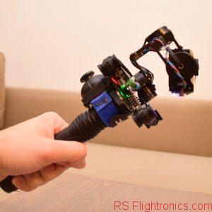
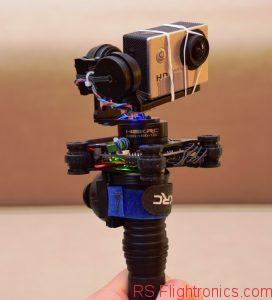
Final words
Here are some pictures of my finished handheld gimbal!


Hi, I’ve seen that so interesting. I’m doing a project similar to it, but the gimbal when it’s in a handled position doesn’t calibrate good and it doesn’t work. Please would you be able to help me?
Hi! you should pay attention to the initial position of the gimbail. I have noticed that if it is somhehow rotated from its precalibrated zero position, then it will have a hard time getting calibrated.