
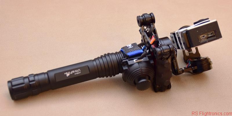
In this instructable for a 3 Axis Handheld Gimbal I will describe the steps to go from a flashlight to a fully functional handheld gimbal. The obtained results are just great and if you are on a budget, this setup is the right one for you, keeping the prices and complexity as low as possible!
Here is a video of the handheld gimbal described in this instructable
The second part of this instructable can be found here.
Contents
What do you need to get started?
- HAKRC Storm32 Alloy 3 Axis Brushless Gimbal (Gearbest)
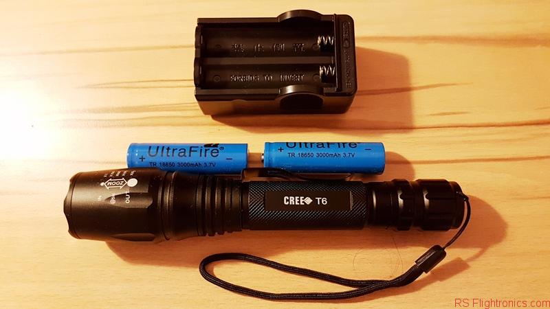
- E02 1600LM CREE XM L T6 5 Modes Adjustable Focus LED Flashlight (Gearbest)
- Male and Female JST Connector Plug Line for RC BEC Lipo Battery (Gearbest)
- Multimeter
- Small file
- M6 x 10mm
Assembling the handheld gimbal
The HAKRC Storm32 Alloy 3 Axis Brushless Gimbal (Gearbest) comes with two bateries and its charger. It is a good idea to leave batteries charging while we start with the first steps.
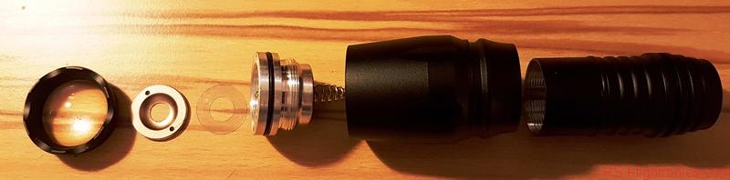
Disassembling the flashlight
As first step, we need to completely disasassemble the flashlight. There are some parts that are not going to be part of our handheld gimbal, and there are other parts that will need to be modified. Our first target is to get to remove the LED element and its electronics and to solder a male connector with its cable to power our handheld gimbal.

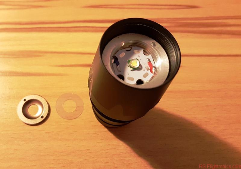
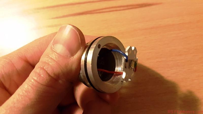
Once the head has been removed, we proceed to dismount all internal parts. A screwdriver can be used to push as indicated in the picture below.

This last action will get the LED and its electronics uncovered.
We still need to loosen one more part before we can remove all the components. We can use just our fingers for this, as shown below.
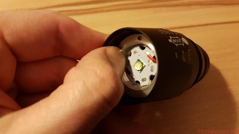
After the step mentioned above, the flashlight’s head has been completly disassembled and now we can proceed with the second part!
Adapting the flashlight
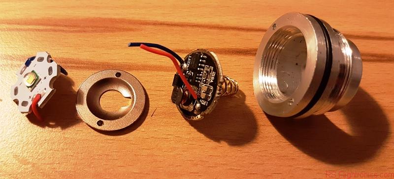
In this second part, we proceed to remove the LED electronics and to adapt its circuit board so we can solder our cable to power the gimbal.
Both cables can be cutted, this will aloow us to remove the LED element.
The bottom part can now be removed with help of a small screwdriver.

In order to get the cables passing through the flashlight’s head, we need to modify the part shown below. A small file can be used for this purpose.

Now we can proceed to discard the LED element, and all the electronics soldered on the circuit board.
This board contains all the electronic necessary to supply constant power to the LED. Since we do not need it, we can remove all its components.
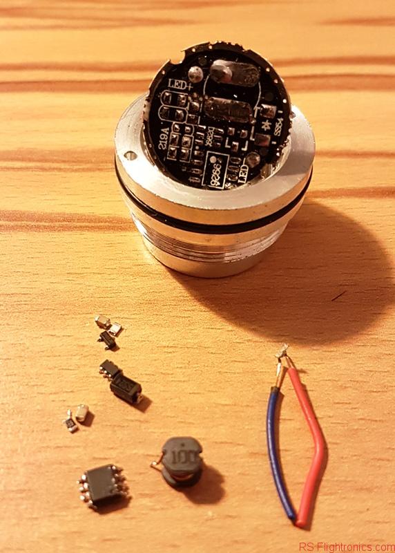
Components can be removed by using a solder tool with a reasonable power. In my case a 60W solder did the work without problems!. It is Important to remark that all the circuitry needs to be removed, in order to ensure that no unexpected behaviour arises.

Once the electronic has been removed, we need to do some slight “correction” to the board in order to avoid collisions of the GND cable with the flashlight body.

Once our board is clean and ready, we can proceed to solder our power cable (Male and Female JST Connector Plug Line for RC BEC Lipo Battery (Gearbest)). Notice that the red cable needs to be soldered on the very same pad as shown in the picture below!.
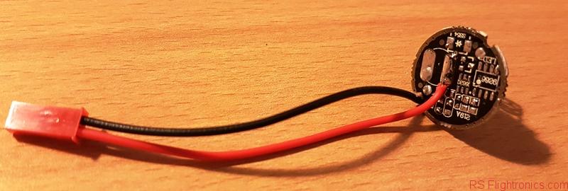
The black wire can be soldered on the bottom as shown below. This should be done close to the modified edge so it can go upwards as shown below.

After this we are ready to remount the circuit board back to its original place.

Now it is time to pickup the batteries that you left charginig at the beggining of this instructable!
We will doublecheck that everything has been connected the right way. For this we need to reassemble the flashlight, the picture below can be taken as reference.
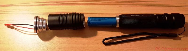

Once the flashlight is assembled, we can proceed to check if the polarity is ok and that the power harness works as expected.
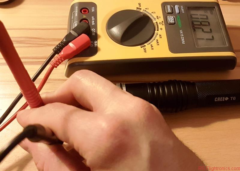
Configure the multimeter to meassure DC voltage, and then proceed to measure the voltage at the end of the power harness. If everything is ok, you should get a reading around 8,25V, with no negative sign, since this would mean that polarity is inverted and this could damage the gimbal electronics. If that is the case, please go to the previous steps and see where exactly the red and the black cable should be soldered.
Putting all together
We are getting closer to the point where our flashlight starts to look like a 3 axis handheld gimbal!!.
On this section, we will proceed to mount the botom plate of the gimbal that is going to be fixed to our adapted flashlight.
In the picture below it can be seen all the compnents needed for this step.
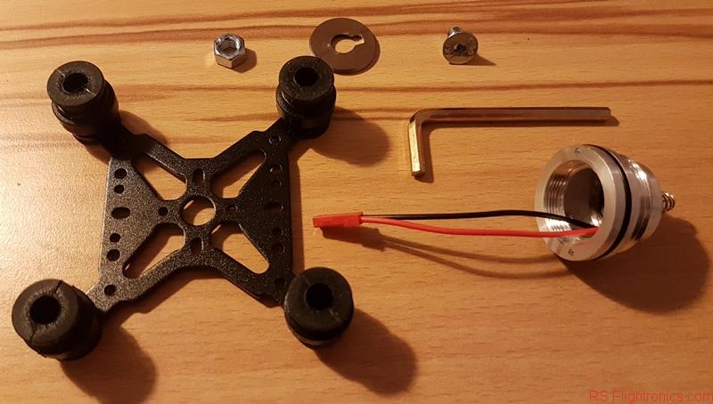
Proceed to mount the screw and our adapted “washer” as shown below.
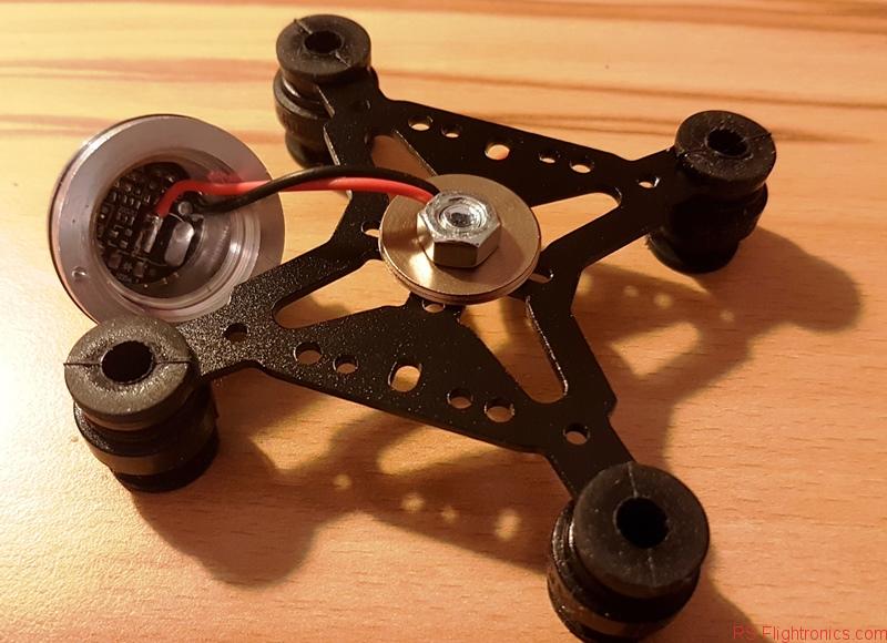
Notice that the cables has been wired through the slot that we made on a previous step.
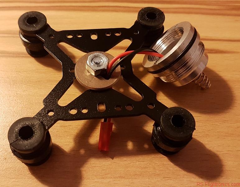
I added some pictures below so you can see further details of this step. Notice that the head of the screw will be facing the bottom side of the gimbal electronics. It is important to find a screw with a low head profile so the gimbal electronics wont be in contact with the screw. This could lead to an undesired shortcircuit!!


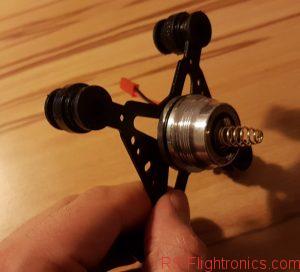
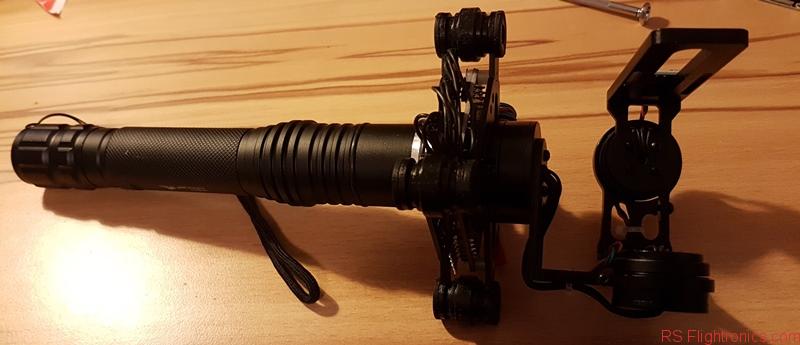
Now is time of connecting part of our gimbal with the flashlight! For that, proceed to mount the flashlight’s head back to its body. At this poitn our creation should be looking something like the picture below. We are almost there!!!!


Now you can mount the missing part of the gimbal. You will need some patiente to mount the rubber dampers.
For the next steps it is extremly important that you have mounted your camera on the gimbal. If not, the gimbal wont work!

Configuring the gimbal
As first step for the gimbal configuration, we need to download a configuration tool from the following link:
Notice that there are several kind of firmware, the one we need is the Firmware for STorM32 setups using I2C IMUs.
You can directly download my config file into your controller 20180223_gimbal_configuration.
The picture below shows where to load the configuration file.

Notice that you still need to click on “Write + Store” button so the config is actually downloaded to the controller.

In the following galery I show you how my config screens look like


Final words
On this first edition, the basics for building a handheld gimbal has been described. A config file is also included so you can have a starting point. The setup steps could require some additional steps, for that I would recommend to look for further tutorials and also to visit the following link, that is the official refernce for the gimbal controller: Storm32 Manuals and Tutorials
The second part of this instructable can be found here.

Original SJCAM SJ6 LEGEND 4K WiFi Action Camera only $123.99

Make a more new posts please 🙂
___
Sanny