
Contents
Introduction
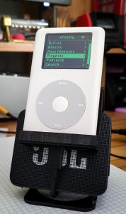
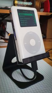
Spotifypod is a modified 4th gen iPod that is capable of running Spotify and streaming audio to a Bluetooth speaker. This post describes the steps needed to recreate what Guy Dupont did in this great implementation: sPot: Spotify in a 4th-gen iPod (2004).
Make sure you first visit his project and get familiarized with the concept. As soon as I saw this project, I knew there was no way back! had to do it 🙂 .
I tried to reproduce what Guy Dupont did, introducing small variations that fitted what I had on my desk at the moment of starting with this build. One of my goals was also to try to reduce costs from the screen side since here in Germany the suggested Adafruit display is not that easy to find.
I take absolutely no credit for this build. This is intended to be just a step-by-step guide for those who would like to have this super cool upgraded 4th gen iPod sitting gracefully on their desk ;).
Another important point to mention: This post is mostly focused on the hardware side. The software side is dynamically being updated in the GitHub repository 😉
In this post, it is assumed that the raspberry pi has been already configured according to the README instructions from the original project.
Having said that, let’s go to the following section!
Part list
The following parts and components are necessary for the Spotifypod build:
- Premium Spotify Account if you want to have full functionality
- Raspberry Pi Zero W
- 1 x Adafruit PowerBoost 1000C
- SD Card (16Gb should be ok)
- 2inch LCD Module ST7789V controller 240 x 320 Pixels
- FFC FPC 8 Stift 0,5mm adapter
- Polyimid tape
- 2 x Schottky diode ( BAT42 )
- 2 x Small Signal Diode (1n4148)
- 1 x button (4.5mm*4.5mm*4.3mm)
- 1 x Mini Vibrationsmotor
- 1 x MMBT3904 NPN transistor
- 1 x 1k Ohm resistor
- 3D printed parts
- Base plate
- Key press extension
- SpotifyPod holder (optional!)
- 1 x Battery 750mAh with JST PH2.0 Connector
- Flat band cable
Please note that the items listed above with a link are intended to be just a reference to show exactly what was used.
iPod preparation
Open the iPod
In order to open the iPod safely and without breaking anything, go ahead and watch some tutorials on YouTube first!
This one was particularly helpful:
Remove “unnecessary” electronics
Once you managed to open it, make sure to remove everything but the clickwheel and the little upper board from the metallic side.

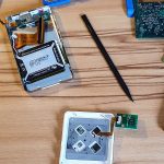
The rest of the parts are not going to be needed for this project.
Isolate the metallic case
Make sure to fill generously all the metallic case surface with Polyimid tape. This will avoid unwanted short circuits later when mounting the electronic components. The 3D printed Base plate will also help to isolate, most of the components from the metallic part, but the Polyimid tape will also cover critical areas, for example, where the Raspberry Pi Zero is going to be mounted.
Display adaption
Since the display will not fit on our iPod, it is necessary to do two carry out two steps:
- Desolder the connector
- Trim the sides. I used a Dremel for this.
After these steps, your display should see like this:


These steps will help us to ensure that the display fits our iPod case and also that you can safely close the case without any internal components colliding.
The required display connections will be later soldered directly on the pads where the connector was previously soldered.
We will come back to this point later.
3D printed parts
These items are optional, not everyone has a 3D printer at home but… it has been helpful to have a plate that makes sure that the components stay at their places and also helps to place the Powerboost at the right height so the usb connector can be accessed from the bottom side. On the other hand, the base plate makes sure that a distance of 2mm is kept from each side so the clips from the plastic lead don’t collide with raspberry py connectors or the battery. The base plate and the other 3D printed parts can be found here: Spotifypod base plate and holder

Electric diagram
Once we have all the components ready to go, we can start connecting altogether.
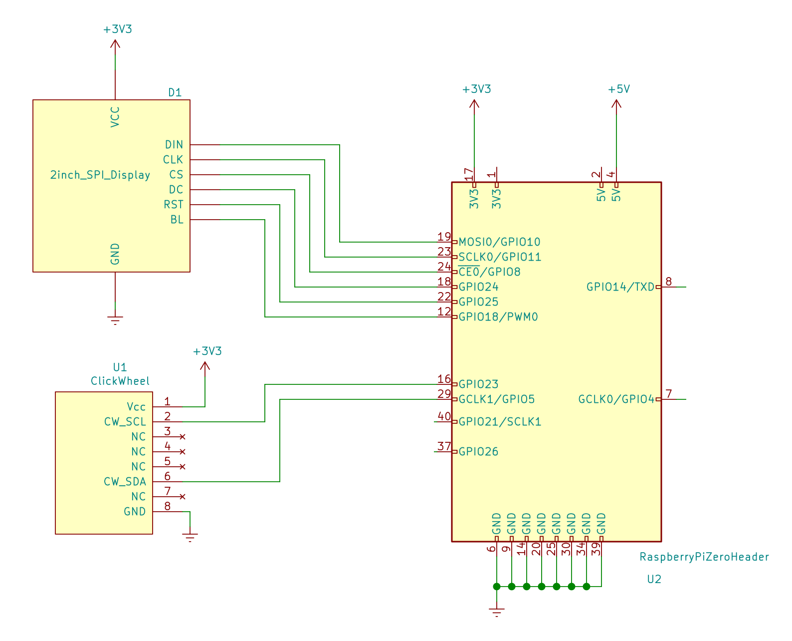
The following connection diagram shows all the modules interconnected. Please notice that there are some variations in comparison with the original project, therefore the implemented software will have some differences when it comes to GPIO configurations. The reason for these variations is that in the original project a composite signal is used whereas for this implementation an SPI display has been implemented. The signals required for this type of interface come in conflict with some of the original GPIOs definitions. Don’t worry, we are just talking about updating a few code lines 😉 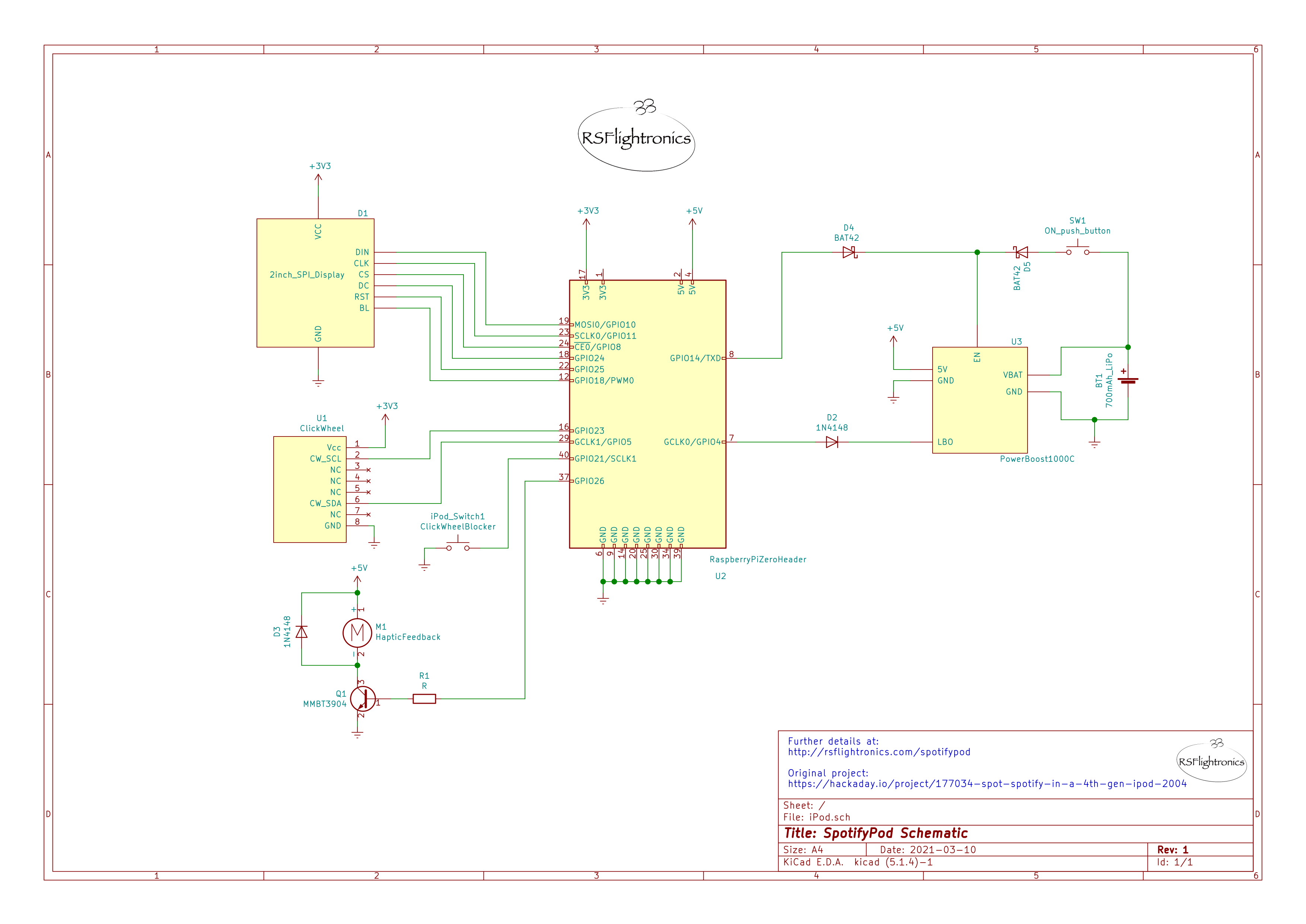 A tip: it is better to start working with the minimal amount of components involved. I would suggest for the first step having just the Raspberry Pi connected with the Display.
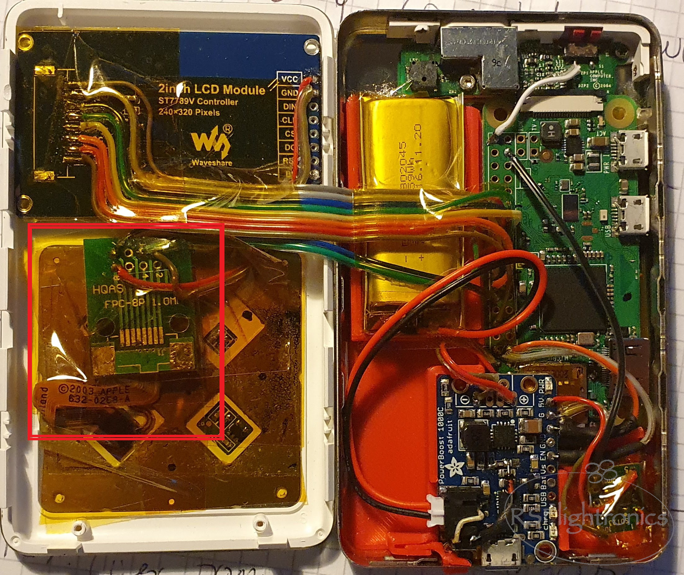
Before starting with the connection, it is a good idea to place the components already in their definitive locations. This will help us to have a better idea about cable lengths and will help to avoid later surprises when trying to close the iPod case.
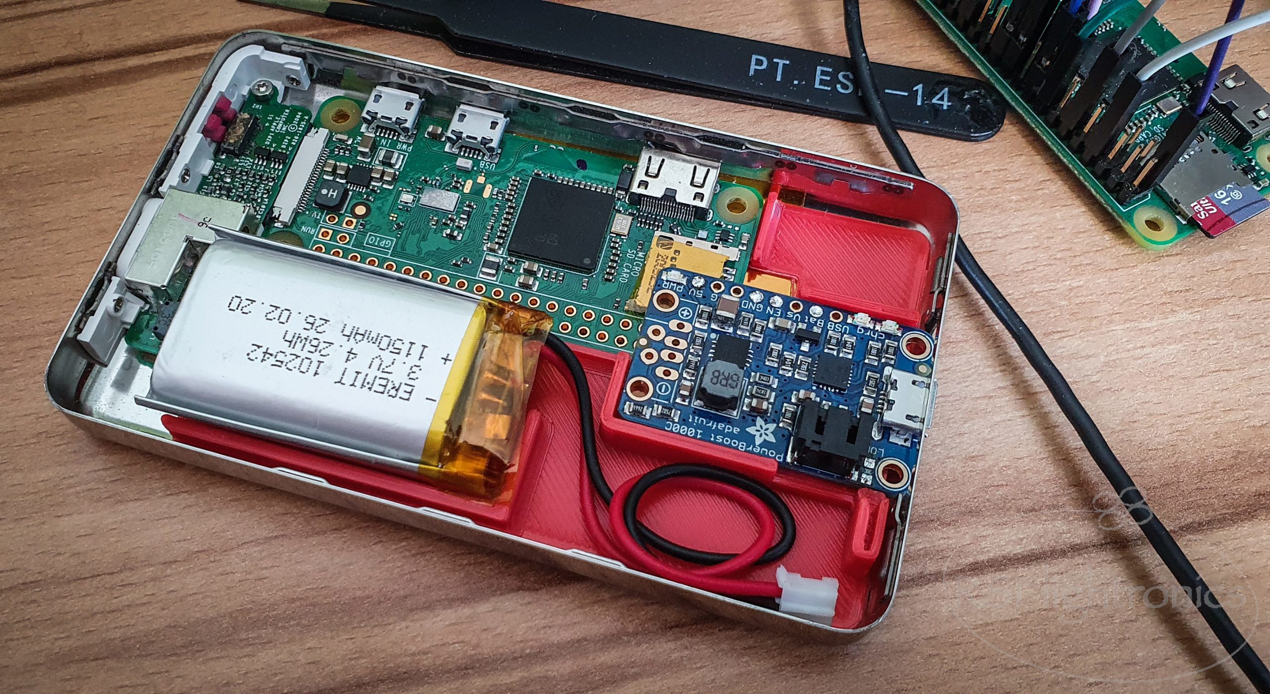
The cable length that you use, should allow opening the case while everything is still connected. This will lead to having longer connections, but you will be thankful later if you have to open the iPod again!. This can be seen in the following picture.

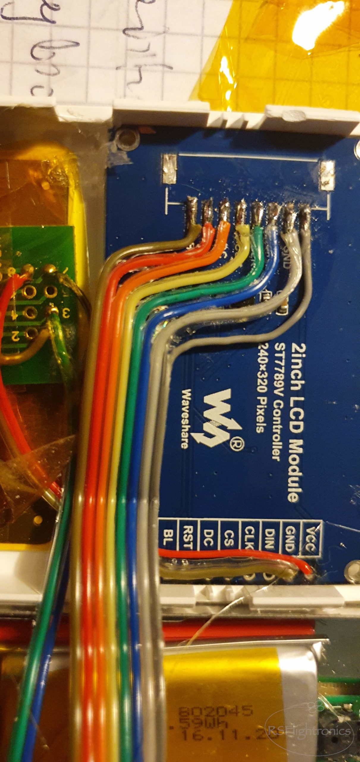
Wiring the Display
We will focus on the following connections only. The whole system can be powered directly from the RPI Zero micro USB connector. Make sure that the display is placed where the original iPod display was. The RPI Zero should be placed on the metallic side held by the 3D printed plate. Start wiring each of the eight signals according to the schematics showed above.
 Once the cabling is done, we need to install the display drivers.
For that, the following GitHub section should help.
The following page was extremely helpful – See Option 2: Mirroring Raspberry Pi HDMI Video to a ST7789 1.3 inch LCD Display
Just make sure that for this setup you use the following cmake options
cmake -DST7789=ON -DGPIO_TFT_DATA_CONTROL=24 -DGPIO_TFT_RESET_PIN=25 -DSPI_BUS_CLOCK_DIVISOR=30 -DSTATISTICS=0 -DDISPLAY_BREAK_ASPECT_RATIO_WHEN_SCALING=ON -DUSE_DMA_TRANSFERS=OFF ..
If the connections are ok and the driver has been correctly installed, you have already a working display!

Clickwheel
It is time to wire the Clickwheel interface! Pay close attention to the pinout!!! I almost fried mine since the pinout description was mirrored on the bottom side :s.
The valid pin numbers for us are the ones from the 0.5mm side. I removed the connector from the 1.0mm side in order to gain more space and avoid possible collisions.
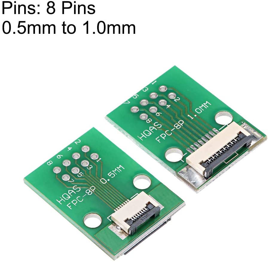
The following picture shows the connection between the clickwheel interface and the adapter.
The Clickwheel will be wired as follow:
 Once again, make sure that the adapter is properly located so the cable length can be estimated. For this build it was placed below the display module and isolated with Polyimid tape:
 Notice that the Clickwheel is powered directly from the display VCC and GND pins, this reduces the amount of “bridges” between both case sides.
Once the wiring is ready, the Clickwheel interface can be tested! Before compiling the source code click.c the following line must be changed:
#define DATA_PIN 25
will be now:
#define DATA_PIN 5
Once the code has been updated, it can be compiled with the following command:
gcc -Wall -pthread -o click click.c -lpigpio -lrt
Once it has been compiled, a “click” file will be generated. Make sure you make this file executable:
sudo chmod +x click
Now you can launch the clickwheel software and test it. If everything runs as it should, you will get feedback every time you interact with the wheel.
Powerboost
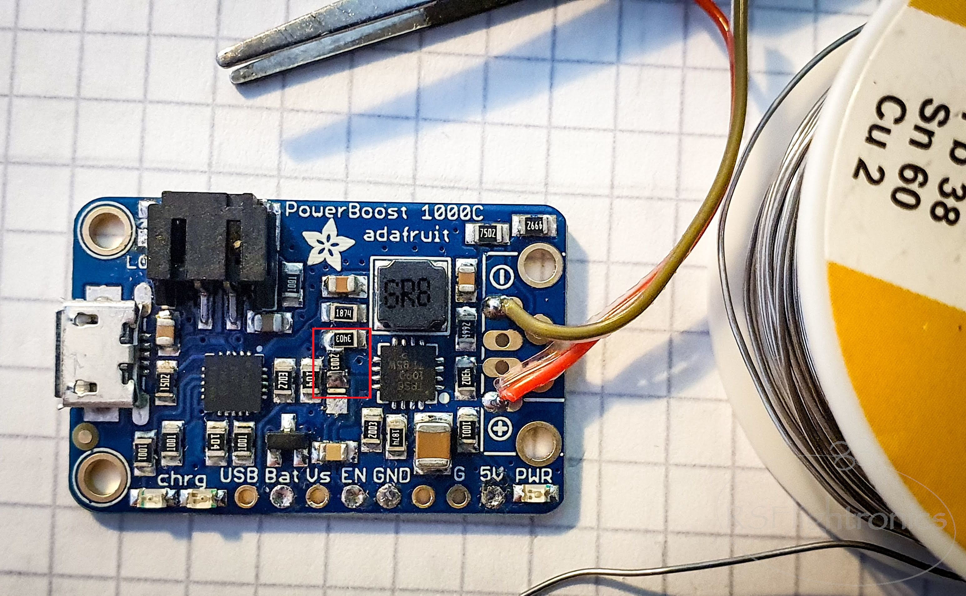
Looking at the original schematic from Adafruit we see that the EN signal is pulled up. That means that the PowerBoost module will be enabled unless we pull the EN pin down. For our implementation, we would like to make sure that unless we pull EN high, the PowerBoost module remains disabled. This behavior can be achieved by connecting R13 directly to ground.

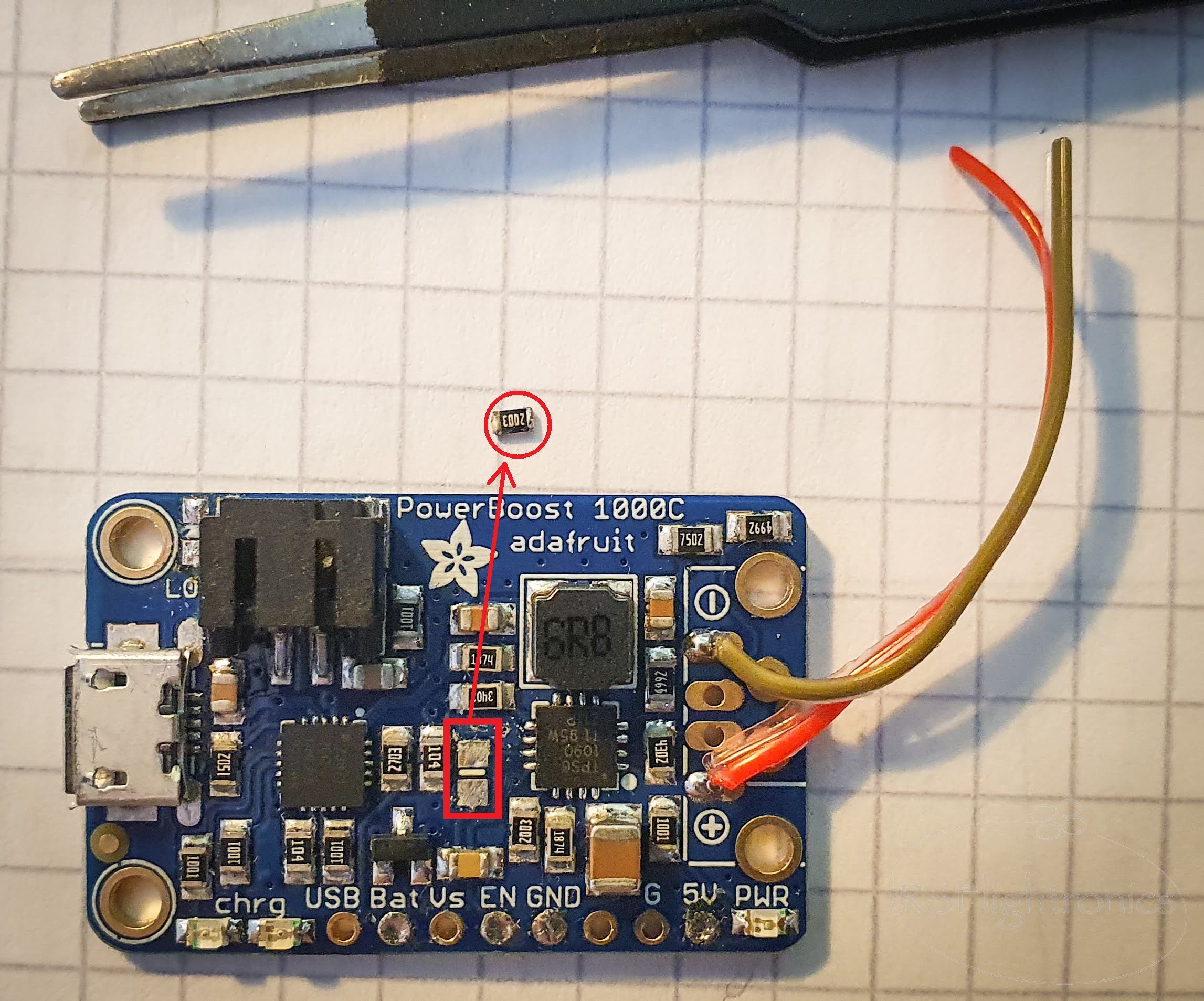
R13 will be placed as shown below so it keeps pulling EN pin down.
The idea is to be able to activate the power boost so it can power up the RPI Zero. But on the other hand, it would be expected that the RPI Zero can be gracefully powered off so no damage to the data structure is made. A concept for this is shown in the diagram below.
- Let us assume that the system is powered off. That means, that thanks to our modification on the PowerBoost module, the EN pin is deactivated.
- Once the Power Button is pressed, the EN pin of the PowerBoost is activated since it is getting its high value from the battery through the schottky diode. At this point, the PowerBoost is activated and providing 5V to the RPI so it starts booting up.
- If the power button until the RPI has initialized the UART module, the UART_TX pin will become automatically high since it is the default status for this interface – Keep in mind that the UART interface must be activated from raspi.config. At this point, the EN pin from the PowerBoost module is still being feed from the battery.
- Once the power button has been released and the UART interface is active, the UART_TXD will be noh holding high the EN pin of the PowerBoost module as long as we keep the Raspberry up and running. At this point, if we execute the command halt the Raspberry will start the power off sequence, and at the end, it will deactivate the UART interface, making UART_TXD pin going back to Low. That means, that no signal will be pulling EN high, therefore, the Powerboost module will be automatically disabled.


Low Battery signal
The PowerBoost module can signalize a low battery status. The signal must be adapted since it is not 3,3v compatible with the expected voltage range input of the RPI. When the battery level is higher than 3,2V, the LBO pin will have VBAT value. When the battery goes below 3,2v LBO will be 0v.
Since VBAT can reach values of 4,7v for a Battery recently loaded, it is important to make sure that we do not let the RPI GPIO be exposed to this “high” voltage. This issue can be easily solved by adopting the following implementation: The principle is more than simple and self-explanatory. In case you are still wondering what it does, here is some help:
The VBAT coming from LBO doesn’t ever reach the Raspberry Pi GPIO port. Only the 0V does. LBO can go from 3,2v up to 4,7v. When LBO outputs VBAT, the diode is non-conducting and thus, the GPIO is pulled to 3.3V by the resistor. When LBO outputs 0V, the diode is conducting and the GPIO is pulled to 0.4V by LBO. The pull-up resistor can be easily implemented as an internal pull-up when configuring the RPI GPIO 😉
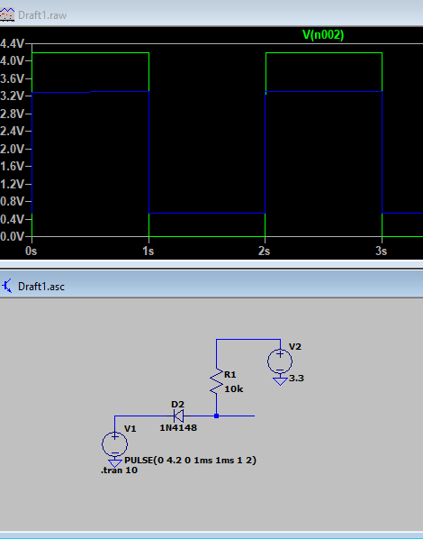 The green signal is the input, LBO with 4.2v and the output is the blue signal. As we can see, the output signal remains within the safe voltage values for the RPI.
Haptic feedback
 Adding a diode in parallel with the motor provides a path for the dissipation of stored energy when the transistor is opened. The flyback diode allows the charge to dissipate without damaging the transistor, or without flowing back to ground through the +5V voltage supply. For further references, the following link contains additional information about this: https://cdn.sparkfun.com/assets/resources/4/4/DC_motor_circuits_slides.pdf
R1 should be 1 KOhm in order to make sure that the transistor switches correctly.
The following pictures show how the haptic motor was implemented. Since here size does matter, I tried to keep it as small as possible!


The motor was then glued below the adapter board and it fitted nicely in the lower right corner. The motor itself is then also glued directly to the metallic case. The first attempt I did was gluing it to the 3D printed base, but the vibration was somehow attenuated.
Make it look nice!
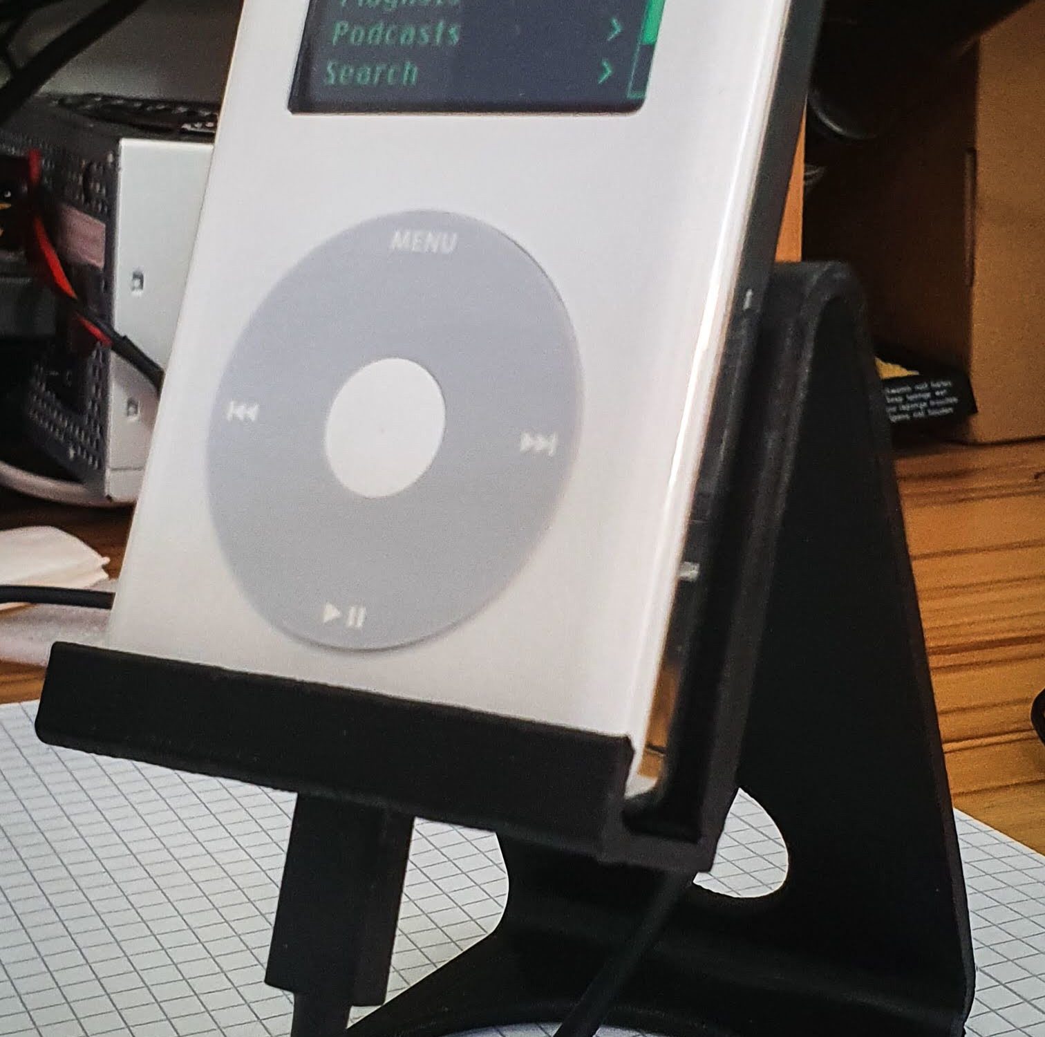
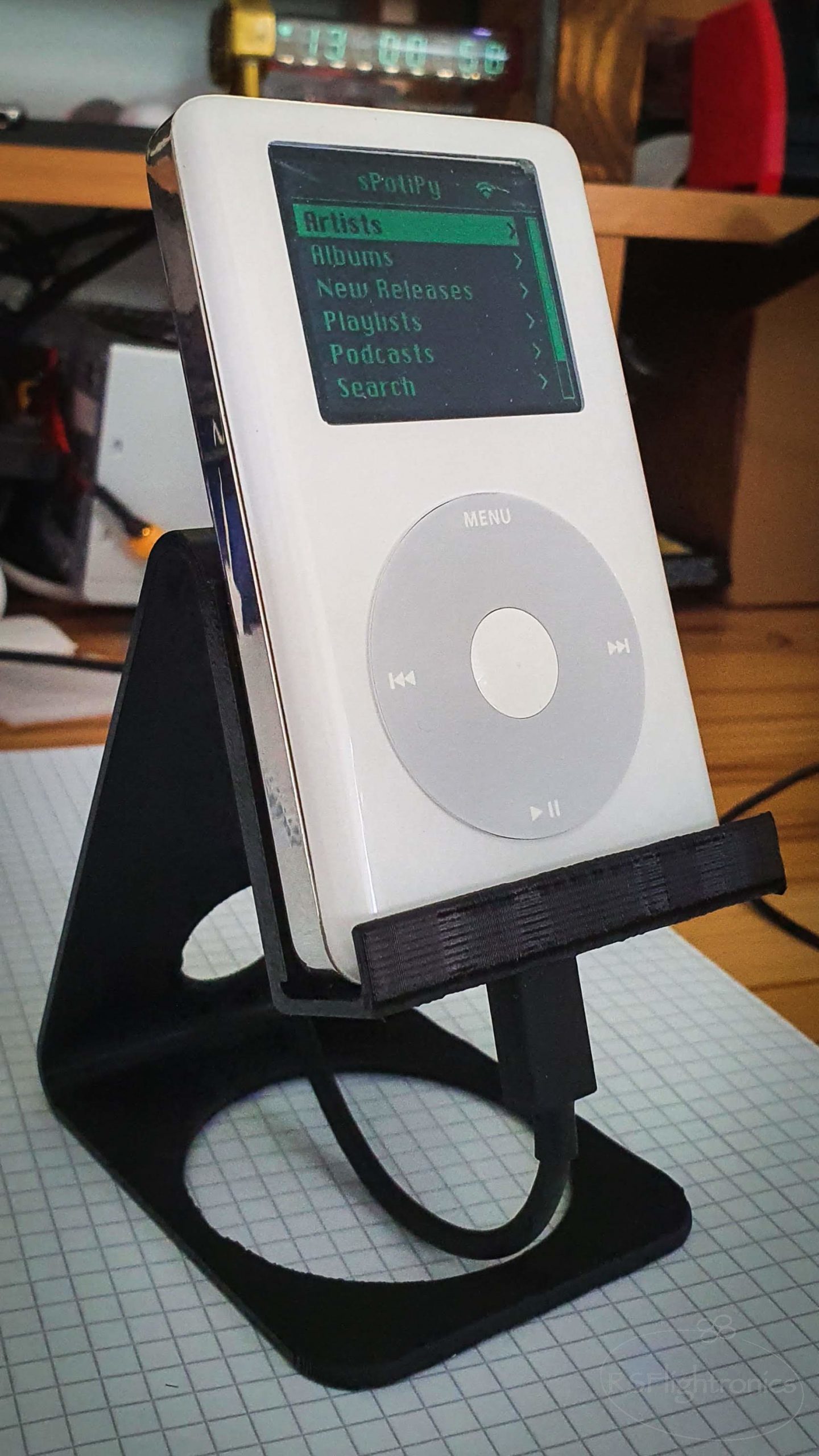
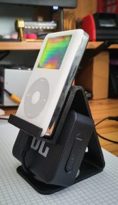
I have included on the 3D files, a support that fits the Spotifypod nicely. The iPod can sit on this support while charging its battery through its USB port.


This is a work in progress! Stay tuned for more 😉

Hi there! very nice project, congratulations!
I think you forgot to add the power booster to the part list please correct me if Im wrong.
Thanks! You are right, the Powerboost was missing!
Incredible work! Would this work in a 5th generation case? Thanks!
I am mot familiarized with the dimensions of the 5th generation case.. if it has the same size it could work.. the only one open question would be if the Clickwheel pinout and protocol is compatible with the 4th generation… Unfortunately I dont have any 5th gen Clickwheel to play around and confirm this :/
I’m actually trying my hand at a project on a 5th generation now, also inspired by Guy’s project! There are some pretty big differences. Clickwheel pinout and protocol is different; the clickwheel on the 5th gen is 14 pins instead of 8. I just bought some 4th generation clickwheels to see if I can use them instead. Also the display size is different, which I’m really struggling with. The 5th gen iPod has a 2.5″ LCD; it’s wider than the 4th gen LCD. The 2.5″ LCD from Adafruit matches for the screen dimensions, but the full width of the LCD’s hardware is the exact width of the iPod enclosure :/ I’d love to trade info and keep track of others’ progress, message me on Twitter @ tetripod if you want to chat more!
Interesting! I was wondering if Apple kept the protocol backward compatibility. Now I see it is not the case… let us keep in touch! I will follow your journey from Twitter 😉
Hi! The click wheel for the 5th gen is not compatible with the 4th gen… The 5th Gen has more pins than the 4th and the protocol itself seems to have some differences. I also don’t have a 5th gen Clickwheel to play around but it would be interesting to do the reverse engineering of that one too 🙂
Thanks for detailed wiring schematics and part list. Now I can make a rPi hat PCB to including everything without messy wiring needed 😀
Since I have so many worned out battery ipods, this project should be interesting to try for me.
Awesome!! Let me know whenever you have the first prototype!
Did you ever make a pcb for this? Would be very interested in checking it out
Great work. For the LBO, is it simply just adding the diode between the pi and the powerboost or am I missing something?
Just the diode… and the software interpreting this input from the PI Zero side!
Hi,
many thanks for posting this, will attempt soon. Quick question on the software side: is it possible to download music on the SD card to use the iPod on the Go? And how is it decided which music from the spotify catalogue ends up in the library?
I think it should be possible, it is all software… one of my weakest points haha. I can imagine that this is possible. I would add an extra input in the main menu to be able to read the internal albums… I would request this feature directly on the Github repo and see what the software experts say 🙂
I can’t pretend to understand everything that is going on here. I’m familiar with software, but less so with electronics, but would like to start to learn. I have a few questions. It seems like the only thing you are using from the original iPod are the case, and the input from the wheel. If you didn’t care about making it look like an iPod, is there a way to build the same functionality with a different input type, say up/down and right/left buttons? Or even a way to simulate the wheel but using non-apple components?
I think I’d like to try and build one but don’t have access to an old iPod, and for a frist project I don’t want to spend the money to buy a used one on ebay.
Hi! Yes! the clickwheel can be replaced and buttons can be implemented there. The buttons can be wired so a matrix is created and reader from the Pi Zero GPIO. I don’t see any issue with zour idea. The only file I see you should update and adapt, would be the clickwheel.c
Hi! I have the screen working but it asks me to log in, is that ok or did I do something wrong? Thanks!
Hi Fernando,
could you please provide more details? Where are you being asked to log in?
Saludos!
Here you can see!
https://drive.google.com/file/d/1bSyXmfa1sM3ZHWH_3ncrAbhijZhpp5An/view?usp=sharing
Hi Fernando, what version of raspbian did you installed? The one I used is the lightest one, where you only get the console. Can you confirm that?
Really nice project. I want to recreate it but have problems setting up the raspberry pi enviroment. What should be set as the Redirect URI? Is it required to work or can it just be anything? Thanks!
Hey mate,
Just wondering if you could elaborate on the Hold switch a little? I see in the schematic it’s to perform it’s original function of stopping input from the clickwheel.
I see it’s connected to a GPIO pin, but I don’t see any other wires going to it, how are you adding ground / power to it?
There looks to be 3 pins on the switch, have you wired the GPIO pin to the middle pin (second from left)?
Also just wondering what is in the bottom right of the ipod? Connected to ground & 5v on the powerboost, I don’t see a reference to it in your schematic.
Hi there,
on the boton right is the haptic feedback module, this is included kn the schematic with the symbol of a DC motor together with a diode and a transistor.
The hold button is connected as shown in the schematic. The RPI gpio is configured as pull-up. When the switch closes then the gpio will “see” a logical zero. Since all the metallic case is connected to ground, I just bridged the nearest ground point of the little upper board to the switch… and wired the other pin to the gpio.. and that’s it!
Where do you check for the logical zero on the software side? Do I need to change click.c in order to reflect the hold button or is this already implemented somewhere in the python code?
Thanks for the nice summary. Especially modifying the powerboost might come in handy on other projects!
Yes, you have to modify click.c and recompile it
Did you use a 20gb or 40gb ipod? from what i can find, the 40gb is a good bit thicker than the 20gb, but neither you or Guy seem to indicate which size you used. I’m sourcing an ipod, and want to make sure everything will fit
I just built one with a 20Gb HP ipod, but of course extra thickness can come in handy. The only difference is I didn’t include the haptic feedback and just used the ipod switch tied between gnd and the Powerboost enable bin – I shutdown the pi zero via software first.
If anyone’s interested, I made a variation starting from this great post. Instead of Spotify, I wrote software to run MPD so that I can play local files from the sdcard and control other MPD players in my house. I also used urwid library for a text based interface (easier for me to code, and I’m guessing it is lighter on resources by running directly on raspberry pi os lite).
If anyone’s interested, I can post the code (though it’s not particularly good).
Yes KIMON I would like the software …Thanks!
Hi. I’m particularly interested in playing local files. That was a change I was going to add. If you still have the code, that would be awesome. I don’t use Spotify.
Thanks,
Doug
Bi! I used a 20GB iPod (Model A1059)
hi, thanks for share!
I want to know how to wire the audio module to pi, should we use an i2s dac to improve sound quality?
Anyone run into trouble with the display drivers?
Keep getting the error message “ensure hmdi_force_hotplug=1” in config, but i have that in there…?
Hello I’m also running into this problem did you by any chance figure out a solution?
I cannot for the life of me get the sPot software to load correctly, especially on the Pi 0 W 1. Is there a pre-configured image to flash? Also it seems raspotifty has dropped support for pi 0 (1)
Hi there! Great write up.
I was wondering if you were having any screen tearing issues with the waveshare screen. I found it quite noticeable.
Thanks,
Hi there, The screen has worked perfectly so far… did you double-check the connections? Are all the cables right soldered?
I do not understand how this all works and I do not know how myself, but it would seem as though one could make a custom PCB for all of this if enough people are interested. Integrate the clickwheel connector and have pads/pins on the custom pcb for mounting the powerboost and pi to. Just an idea I had not know much about how it all works
Sure! It would be a great idea, but in order to do that, some funding would be necessary
Just getting going on this build now, thank you for the detailed instructions. Wondering if you manage to incorporate the headphone jack in some way as has been done in part two of the original build?
Hi Doug, I had this in my ToDo list but unfortunately didn’t have the time to implement it :/
No worries. I’ll get a DAC module and see if I can work it out!
Thanks for letting me know.
Hi there, the “missing board” is just a generic SOT23 adapter that i used to solder the transistor and resistors related to the haptic feedback control.
Check this out:
https://www.ebay.de/itm/334724198673?mkcid=16&mkevt=1&mkrid=707-127634-2357-0&ssspo=sfgUJa-QQLu&sssrc=2349624&ssuid=&var=&widget_ver=artemis&media=COPY
Great Project!
I was just wondering how long the battery lasts withoit recharging?
Hi Lukas, the battery lasts a few hours according to my experience. I never focused on optimizing this point to be honest 😅
Trying to reverse engineer the clickwheel for the iPod classic gen 7, anyone knows what kind of pin layout this is, and what connector I should buy?
https://imgur.com/a/3qIBo58
Is it possible to implement a balanced DAC in this build, I do understand that space management is a huge factor in this build but the simple fundamental charm of the headphone jack would be really important for a lot of people, is it possible for the raspberry to use the headphone jack from the hold switch module but wired from a different DAC chip like one intended for a phone (ESS Sabre ES9219MQ) but stripped down to be used by the raspberry pi. This makes sure that the user gets the best audio quality from a device deigned solely for everyday music. Thankyou
I think it might be possible!